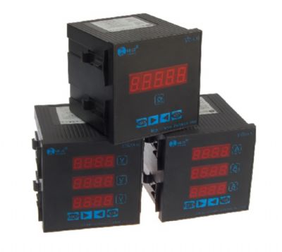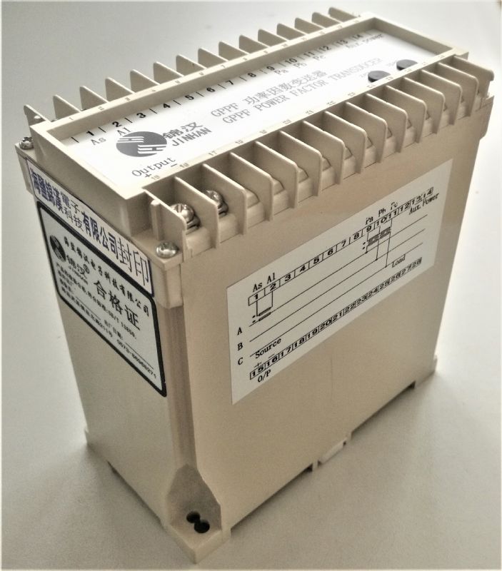
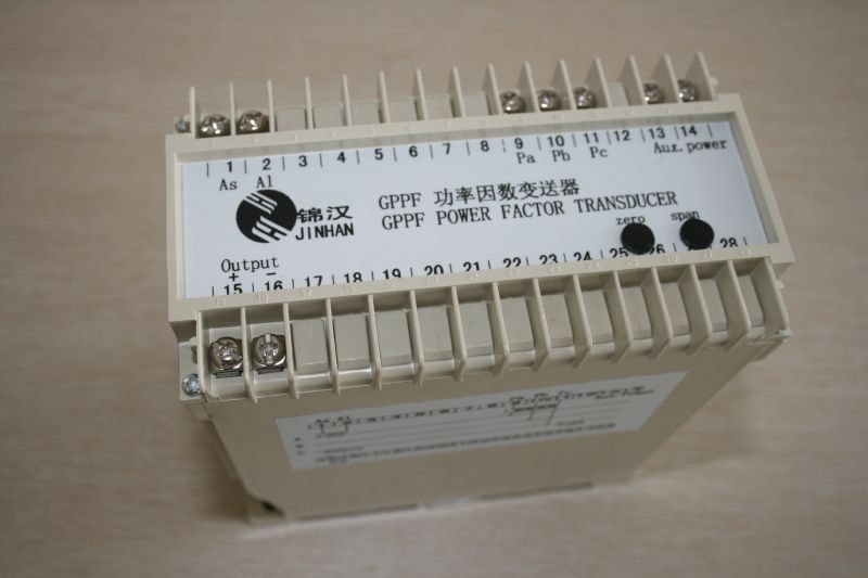
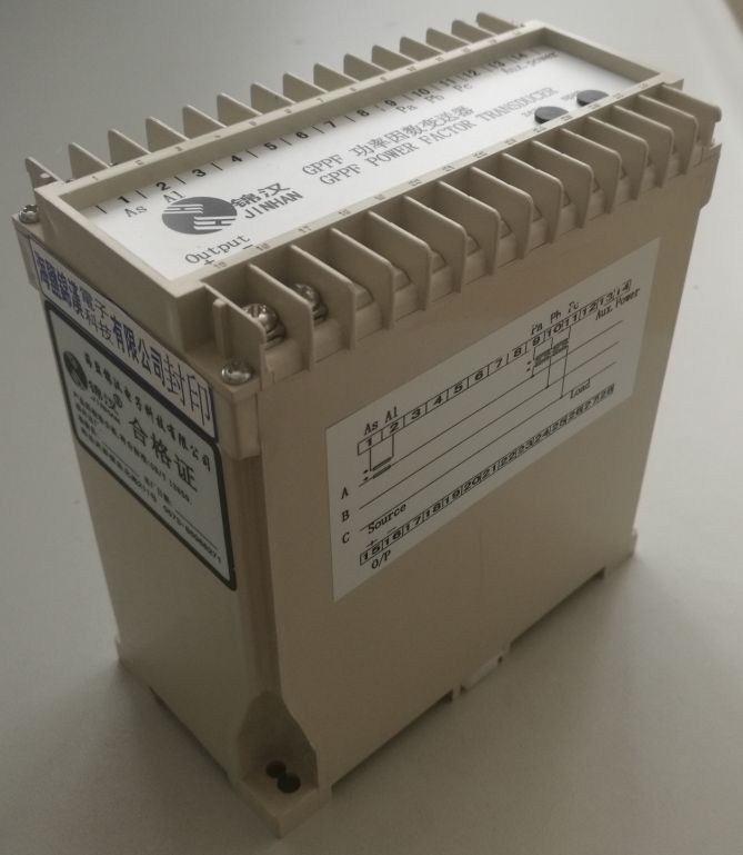
GPPF POWER FACTOR TRANSDUCER
Quick Overview
The zero-crossing detector modulation conversion principle is used to produce a corresponding linear DC output signal proportional to true power factor of the power system. The transducers can be use in a single or three phase system.


Related Products

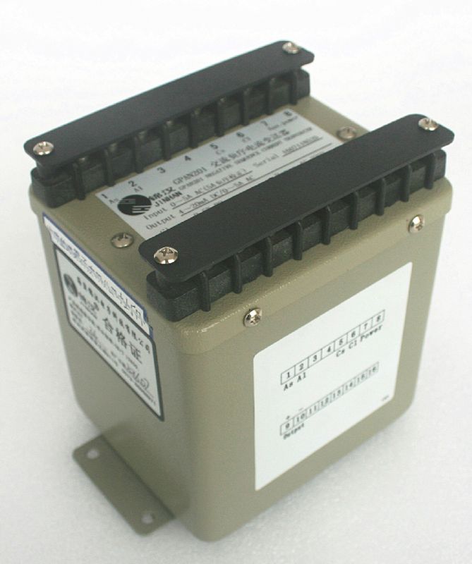
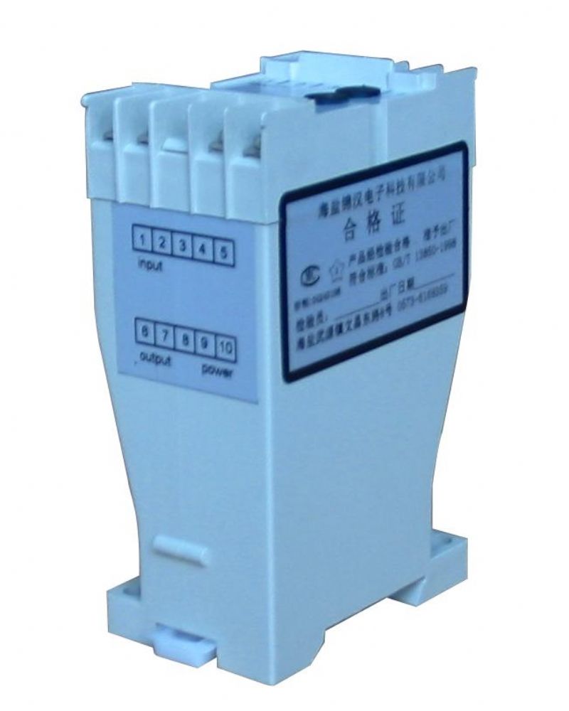
GPPF POWER FACTOR TRANSDUCER
1. Introduction:
The zero-crossing detector modulation conversion principle is used to produce a corresponding linear DC output signal proportional to true power factor of the power system. The transducers can be use in a single or three phase system.
Applied Standards & Rules
Measuring and conversion : IEC 688 / 1992 - 04
Dielectrical strength: IEC 688 2KVac / 1 min.
Surge and Impulse test: ANSI C37.90 / 1989,IEC 255-3 (1989) 4KV 1.2 x 50 us
Reference Standard: GB/T 13850-1998(IEC688-1992)
Models and specifications:
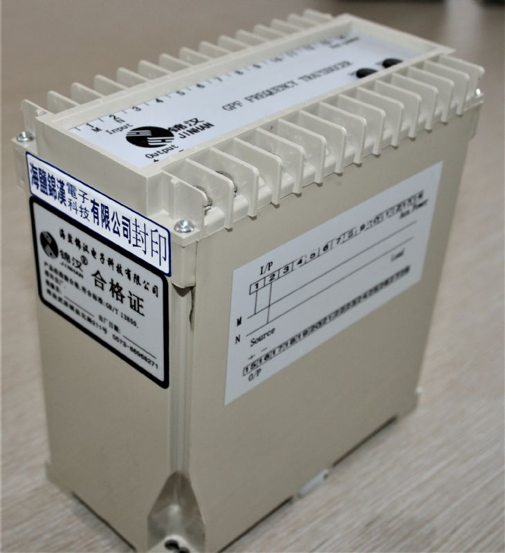
GPF - Frequency Transmitter: Accuracy: 0.5%
2.Specification:
Reference Standard: | GB/T 13850-1998(IEC688-1992) |
Accuracy: | 0.5%RO according to IEC 688-1,At(23±5℃) |
Long term stability: | ≤±0.5%/year,No accumulation error |
Temperature influence: | <100ppm/℃ |
Response Time: | <400ms |
Output Ripple: | <1.0% (peak-peak value) |
Input burden: | Current less 0.2VA;voltage less 0.1VA |
Frequency: | Nominal frequency ±10% |
Maximum output load: | Current output Max10V pressure drop Voltage output rated 2mA MAX 5mA output |
Auxiliary power: | WATT unit: <3.5VA, |
Auxiliary load effect: | <0. 2 % |
Allow excessive input: | Current 2 rate continuous 20 rate 1 secs voltage max 2 rate continuous |
Dielectric strength: | Input/output/power/betwem the crust 2KV,AC 1 min IEC866 |
Impact test: | ANSI C37.90a/1973,IEC 255-4,(5kV 1.2/50us Pulsed Voltage) |
Calibration amplitude: | Full scale least<±3%,zero least<±1% |
Magnetic field effect: | 0.4KA/m magnetic field strength change<0.05% |
Operating condition: | Temperature -10~55℃relative humidity ≤95% RH non condensing |
Storage condition: | Temperature-40~70℃ relative humidity ≤95% RH non condensing |
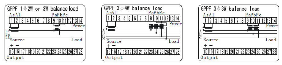
3.Trminal Connection:
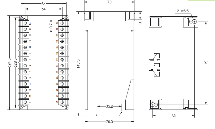
4.Dimensional Drawings:
1.Order form:

Input & Output parameters
Vn : Voltage input | Vn rating range | V1 100 | V2 220V 180-300V | V3 400V 320-450V | Vy Specified | On : Output | ||
An : Current input | An rating range | A1 1A 0-1.2A | A2 5A 0-6A | A3 10A 0-12A | Ay Specified | O1 0-1mA | O2 0-20mA | O3 4-20mA |
Fn : Frequency input | Fn rating range | F1 50Hz 45-55Hz | F2 60Hz 55-65Hz | F3 400Hz | Fy Specified | O4 0-5mA | O5 0-10mA | O6 4-12-20mA |
Pn :
| Pn rating range | P1 AC110 V 120 V ± 15% | P2 AC220 V 240 V ± 15% | Ps Internal Power | Py Specified | O7 0-1V | O8 0-5V | O9 0-10V |
PDn rating range | PD1 DC110V 120 V ± 15% | PD2 DC220V 240V± 15% | PD3 DC24 24 V ± 20% | PDy Specified | O10 2-10V | O11 1-5V | O12 1-3-5V | |
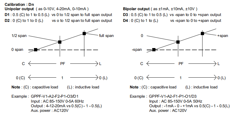
Dn Power Factor Emendation | D1:0.5C―1―0.5L 0―1/2full scale― Positive full scale | D2:0C―1―0L 0―1/2full scale ―Positive full scale | ||||||
D1:0.5C―1― 0.5L Negative full scale―0―Positive full scale | D1:0C―1― 0L Negative full scale―0― Positive full scale | |||||||