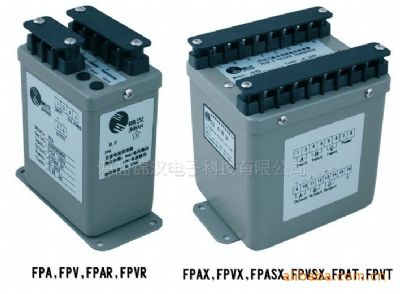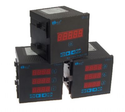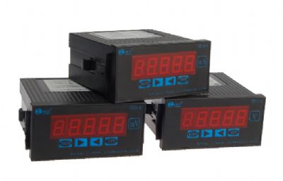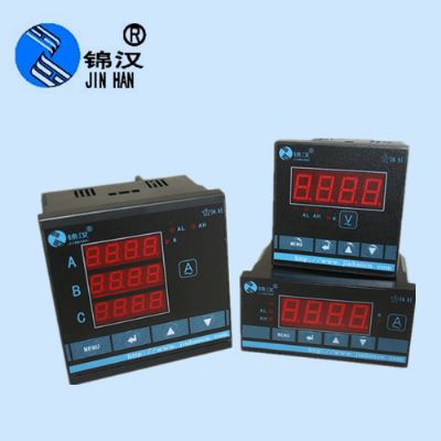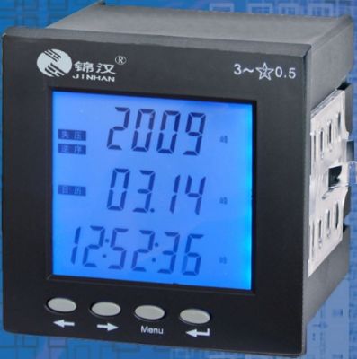


Related Products

1.EATURES
◆Excellent long term stability (4 ~ 20mA, 500W)
◆Precision measurement even for distorted wave
◆High impulse & surge protection (5KV)
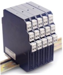
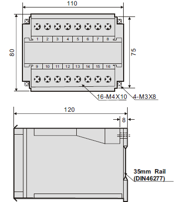
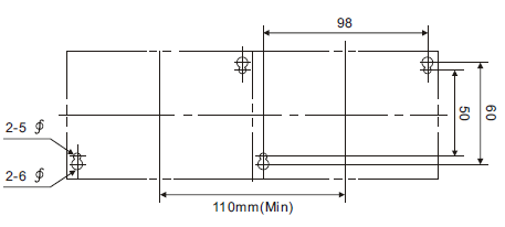
◆The case can be mounted on a 35mm rail which complies with DIN 46277
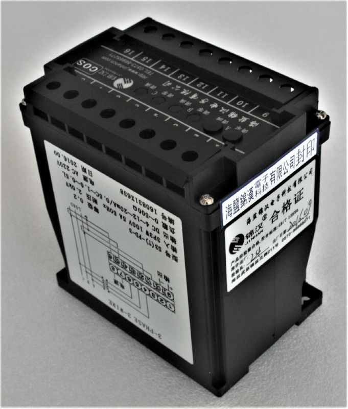
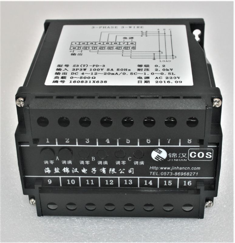
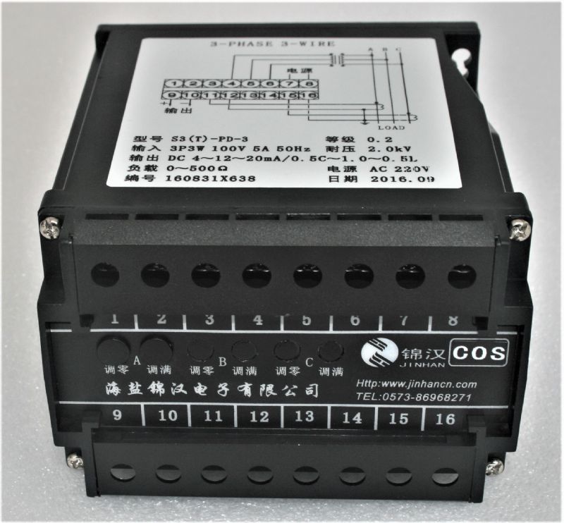
2.DESCRIPTION
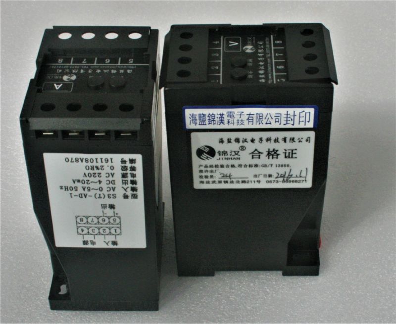
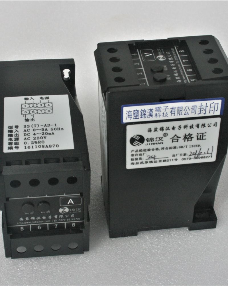
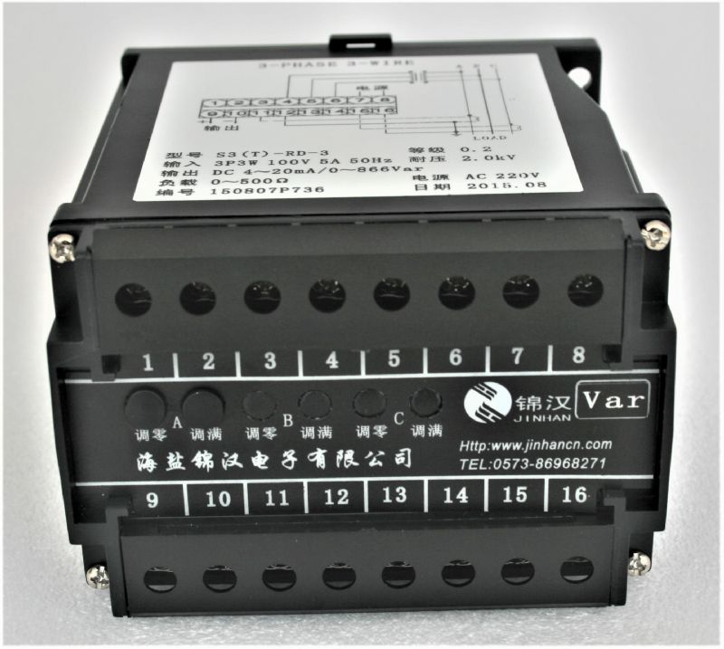
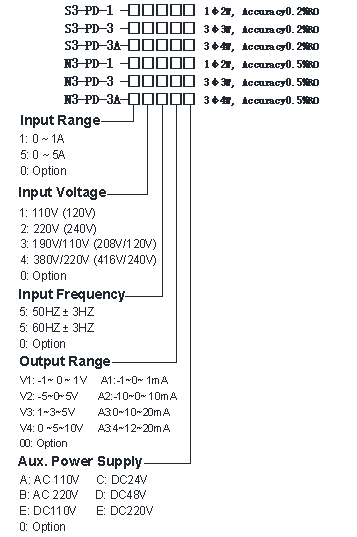
◆Model:
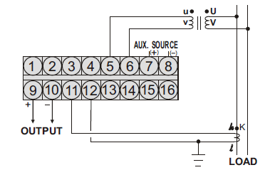
S3-PD-1 :1φ2W,Class: 0.2%RO;
N3-PD-1 :1φ2W, Class: 0.5%RO
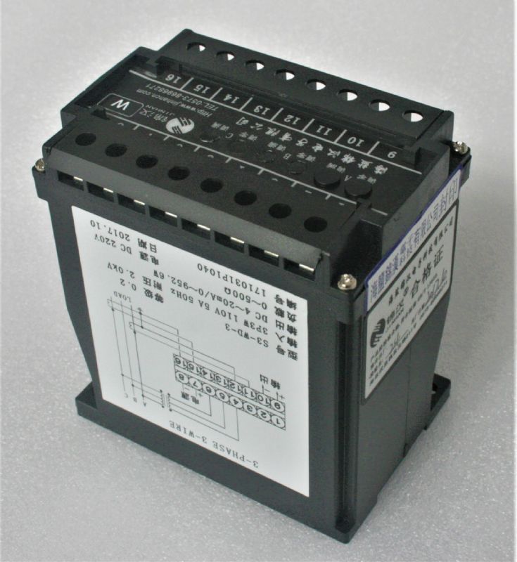
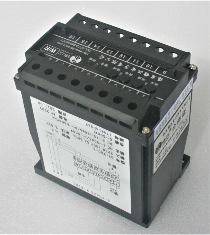
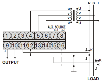
S3-PD-3 :3φ3W, Class: 0.2%RO;
N3-PD-3 :3φ3W, Class: 0.5%RO
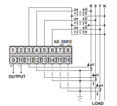
S3-PD-3A:3φ4W, Class: 0.2%RO;
N3-PD-3A : 3φ4W, Class: 0.5%RO
These transducers require an auxiliary power supply and offer a highly accurate method of measuring the phase angle of the input. They have a full four quadrant capability. The output is a linear function of the phase angle between the two inputs (which can be current or voltage), the circuit can also be used as power factor transducer only added a COS circuit.
Output amplifier provides constant voltage or current output. Output is unaffected by load resistance provided it is within the specified range.
3.SPECIFICATION
3.1 INPUT
Input Range | Max. Input Over Capability | |||
Circuit | Amp. | Voltage | Range | |
Single Phase |
5 A | 110V (120V) |
(Lead) (Lag) 0.5 ~ 1 ~ 0.5 or (Lead) (Lag) 60 ~ 0 ~ 60 |
Ampere: 3 x rated continuous 10 x rated 10 sec. 50 x rated 1 sec.
Voltage: 2 x rated continuous |
220V (240V) | ||||
3-Phase 3-Wire |
5 A | 110V (120V) | ||
220V (240V) | ||||
3-Phase 4-Wire |
5 A | 190V/110V (208/120V) | ||
380V/220V (416/240V) | ||||
3.2 OUTPUT
DC Output Range | Load Resistance | Output Resistance | Output Ripple | Response Time |
-1 ~ 0 ~ 1V |
1KW |
<-0.05W |
<- 0.5% RO. (Peak) |
<-400mS. 0 ~ 99% |
-5 ~ 0 ~ 5V | ||||
1 ~ 3 ~ 5V | ||||
0 ~ 5 ~ 10V | ||||
-1 ~ 0 ~ 1mA | 0 ~ 10KW | 20MW | ||
-10 ~ 0 ~ 10mA | 0 ~ 1KW |
5MW | ||
0 ~ 10 ~ 20mA | 0 ~ 500 W | |||
4 ~ 12 ~ 20mA |
Aux. power supply | AC 110V ± 15%, 50/60HZ AC 220V ± 15%, 50/60HZ DC24V, 48V, 110V, ± 15% |
Power consumption | -2.5VA, ≤DC 3W |
Power effect | ≤0.1% RO |
Waveform effect | ≤0.2% RO. at distortion factor 30%( PCIR) |
Output load effect | ≤0.05% RO. |
Magnetic field strength | -0.2% RO., 400A/M |
Span adjustment range | 5%RO |
Zero adjustment range | 1%RO |
Operating temperature range | 0 ~ 60℃ |
Operating temperature range | 0 ~ 60℃ |
Storage temperature range | -10 ~ 70℃ |
Temperature coefficient | - 100PPM from 0 to 60℃ ≤ 60PPM, 25。C ± 10℃ |
Max. relative humidity | 95% |
Isolation | Input/output/power/case |
Insulation resistance | 100M W, DC 500V |
Dielectric withstand voltage | Between input/output/power/case (IEC 414, 688,ANSI, C37) AC 2.6KV, 60HZ, 1 min. |
Impulse withstand test | 5KV, 1.2 X 50μS (IEC 255-4, ANSI C37 90a) Common mode & differential mod |
Performance | Designed to comply with IEC688 |
Safety requirements | IEC 414, BS5458 |
5.3 S3-PD-3A, N3-PD-3A (3φ4W)
1. Model:
S3-PD-1 : 1φ2W,Class: 0.2%RO;
S3-PD-3 : 3φ3W, Class: 0.2%RO;
S3-PD-3A : 3φ4W, Class: 0.2%RO;
N3-PD-1 : 1φ2W, Class: 0.5%RO
N3-PD-3 : 3φ3W, Class: 0.5%RO
N3-PD-3A :3φ4W, Class: 0.5%RO
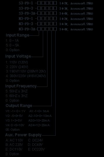
2.Order form:
2. Example of model and parameter filling:
(1) S3-PD-3-555A4B
0.5%RO, 3φ3W power factor transducer
Input nominal current: 5A;
Input nominal voltage: 100V;
Input signal frequency: 50±5Hz;
Output range: 4~12~20mA;
Correspond to -0.5 (capacity) ~1~0.5 (inductive);
Auxiliary power supply: AC220V.
(2) S3-PD-3A-165A5B
0.5%RO, 3φ3W system power factor transducer
Input nominal current: 1A;
Input nominal voltage: 57.7V;
Input signal frequency: 50±5Hz;
Output range: -20~0~20mA;
Correspond to -0.5 (capacity) ~1~0.5 (inductive);
Auxiliary power supply: AC220V.
Note:
1 If the user needs other special calibration, please indicate the parameter value in the contract.
2 power factor input, output value conversion:
y = a1cosф+b1(ф:0 to 60°)
y = a2cosф+b2(ф:0~-60°)
In the above formula: y is the output of the power factor transducer, and y, a, b should be selected according to the different output modes of the powe